Here’s why designing for additive manufacturing still hasn’t been adopted by the majority of companies. Traditional Fixture design is driven by the capabilities and limitations of the machines we make them on. Manufacturers will most frequently use 3-axis CNCs or manual machine tools to create shop floor fixturing.
In order to be both time and cost-effective, these fixtures tend to remain very bulky. This is because manufacturers want to limit the time spent on production equipment, and spend more time making customer’s products. This results in companies viewing the production of fixtures as a non-value-added activity, despite their importance in producing final products.
The problems these manufacturers end up coming to us about are their machine time (i.e. part lead time) and lack of available manpower resources. Lead times to get parts in a machine shop are often calculated in weeks, and when you do finally get machine time, you end up disrupting or delaying something else. Once you have the machine, you’ll either need a machinist to write the code or manually do the work themselves. So you need a skilled operator capable of doing the job.
Although we generally manufacture complex parts with organic geometries, we often end up with the “blocks on a plate” fixture design. However, this makes sense. We want to limit the time we take on our machines and our stock material usually comes in square bars, tubes, or sheets. This status quo leaves us with long lead times, big bulky fixtures that need to be stored around our facilities, and a high cost-to-part ratio when we consider the cost of labor and machine time.
The Additive “Quick Fix”
In response to these challenges, many manufacturers have adopted the additive “quick fix” solution. They’ve turned to additive manufacturing to try and address internal time and resource challenges.
Without having to make any design changes, the printer immediately offers a release valve on the machine shop queue and turns around parts faster, running unattended both day and night. It allows for cheaper fixture production, not requiring any manual labor while utilizing a variety of materials to meet part requirements. In many cases, it also offers an instant ergonomic improvement over a solid metal counterpart.
So when we check in with manufacturing users of FDM we see a lot of these designs.
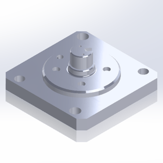
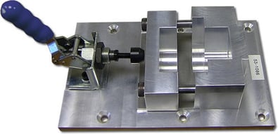
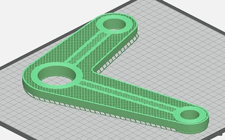
This is an example from one of our customers. They make 12 of these fixtures every year out of aluminum. Their shop is always busy, so they end up outsourcing their production. With their current methods, one fixture costs them over $3,000 and takes 4-6 weeks to procure. This scenario is all too common when we talk with manufacturing companies.
Compare that with a solid ABS 3D printed fixture. The cost would be $190 and take about 19 hours, a little less than a day, to produce.
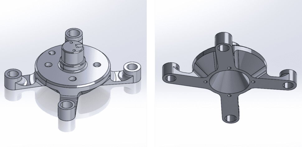
When we apply design for additive principals we can take these improvements a step further. By using the design seen above, we can again drop the cost to $76 and the print time down to 11 hours. That’s a 60% cost and 42% time savings, compared to printing the traditional design.
Common Mistakes When Designing For Additive Manufacturing
Before we get into the best design practices, I wanted to go over a couple of misunderstandings about design for additive and highlight 2 common mistakes I see people make.
The phrase “design for additive” is an extremely broad term. You can think of it as one level down from a term like “design for manufacturing”. Sometimes people will get confused when they ask us about design for additive and we ask, “What are you trying to do?” and “What machine are you using?”
This matters because every type of 3D printer has its own set of best practices. There are dozens of types of 3D printers now, names like FDM, SLA, Polyjet, Binder Jet, DMLS, etc. Each have variations within that sub-family. Just like how a mill and lathe have different design principles, each additive system will have a unique set of rules.
Many people also assume that additive manufacturing solves all their problems without any drawbacks. While additive is extremely versatile and has made huge impacts in manufacturing, it is not the silver bullet solution it can be played out to be. One example of this could be components you can easily source for cheap. We’ve had requests to print parts you can buy online for a few cents, like bolts, screws, and others. We need to understand and evaluate what applications require 3D printing, and when mass-produced components are a better option.
Common Mistakes
The two most common mistakes we see when designing for additive manufacturing are shelling and hollowing of FDM 3D printed parts. I’m not referring to no or extremely sparse infill, rather I mean modeling in hollow cavities in part geometry in attempt to save money on material costs.
Almost every time this has the opposite of the intended effect. FDM printers require support material for overhangs. When designers hollow or shell parts, they often create very large overhangs that need to be re-filled with support materials. Sometimes hollowed-out parts can have support material that is impossible to remove after the print is complete!
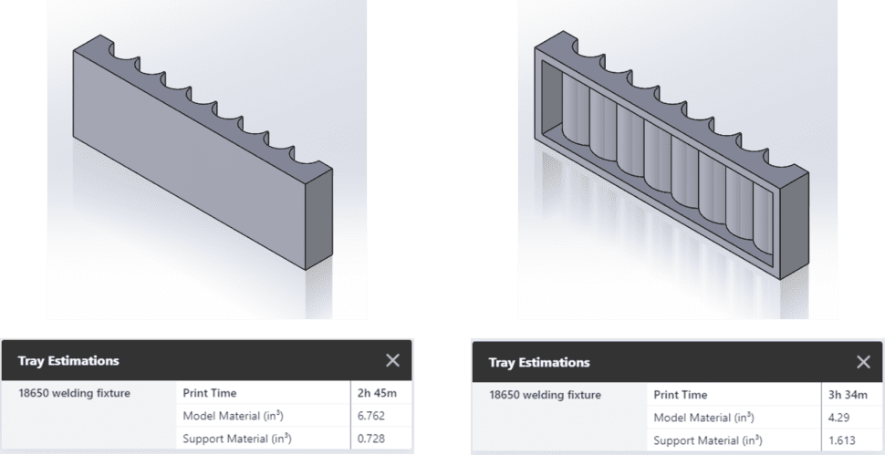
In this shelling example, we have a slight reduction in overall material usage, but our build time has increased almost an hour. This is because systems that switch between model and unique support material are constantly having to switch every layer between the two materials.
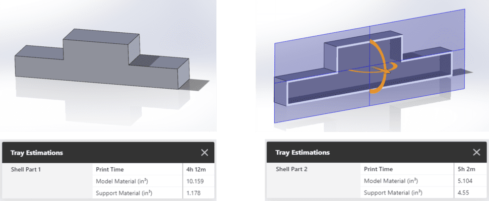
Hollowing again shows us a slight decrease in overall material usage but an increase in print time. On top of that, this scenario creates trapped supports that can never be removed from the final print.
6 Design For Additive Rules for FDM
Now that we understand the challenges and misunderstandings of designing for additive manufacturing (DFAM), let’s dig into some of the easiest and most common design rules you can use with your FDM printer.
1. Self Supporting Angles
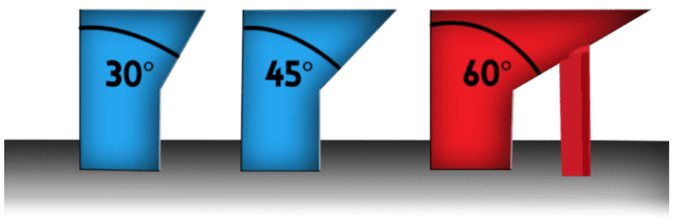
Sometimes referred to as the 45-degree rule, this rule states that FDM parts do not need supports as long as overhangs are less than 45 degrees from vertical. This is one of the quickest and easiest design changes you can make to existing parts. It will reduce support material usage and shrink print times. One important note to this rule is not all materials use 45 degrees as the cutoff. This will vary by material type, generally falling between 40 degrees and 60 degrees.
2. Eliminating Material From Bulky Features
Elimination of material from bulky features is usually what engineers are going for when they design shell or hollow parts. It is true you can greatly reduce material usage when 3D printing, but we need to be mindful of how we do it.
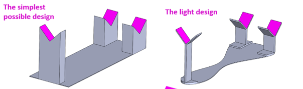
One of the tricks you can use when trying to eliminate material is to focus on mating surfaces. Start by designing contact points, like the pink seen above, where the part will interact with the fixture. From that point, your design can be based on the end goal of the part, whether that’s adding additional strength or generally light-weighting.
3. Selective Strength By Faces
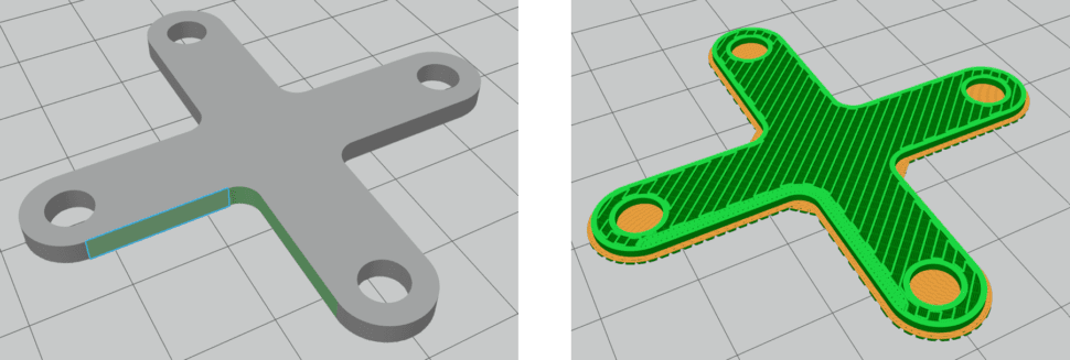
Selective strength by face is another tool used to design lightweight parts while maintaining structural integrity. GrabCAD Print allows users to import native CAD geometry; things like faces and bodies can be referenced within the program. We can select individual bodies and faces and specify infill densities and wall thicknesses. This allows us to only put material where we need added strength so we don’t have to print the entire part completely solid.
4. Selective Strength By Body
Just like selective strength by face, selective strength by bodies allows users to control infill levels between separate CAD bodies. This is a simplified example, but by adding thin bodies within a part, you can create structural ribs, ensuring mechanical performance while maintaining a sparse, lightweight part.
5. Metal Inserst
Metal inserts are an excellent choice if an area of a 3D printed part is going to see excessive wear. Instead of constantly having to re-print the whole part, placing a metal insert like a nut, washer, or heat set threaded insert will allow for greater part life.
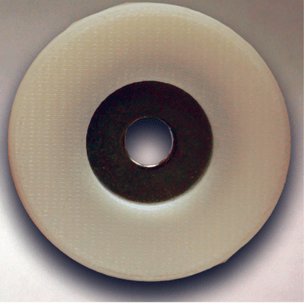
Embedded inserts like nuts and washers require a hole be modeled into CAD geometry where they will be placed. To include a washer or nut in your print, set your printer to pause a layer or two before it caps off the hole where the insert will be placed. This allows you to go to the printer, drop in the insert, and resume printing. If you are printing directly onto a metal surface, we recommend you spray the metal mating surface with an acrylic spray to ensure print quality.
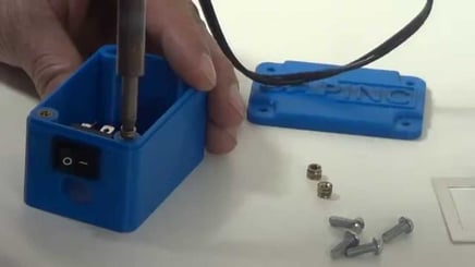
Heat set inserts allow for repeated threading that bare plastic cannot withstand. These are placed after printing using a soldering iron. It’s important that you leave a little extra solid material for the insert to bite into on the sides of the hole where it’s going to be placed. Within GrabCAD Print you can specify what size insert you plan on using and the software will automatically change the hole size and provide extra wall material.
6. Consolidated Assemblies
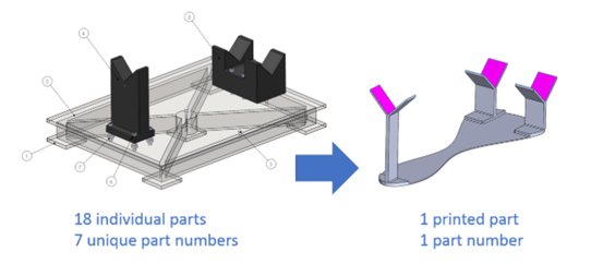
Going back to the bulky fixture example, we can see that printing this part reduces the number of parts from 18 to 1, and can be manufactured without any assembly.
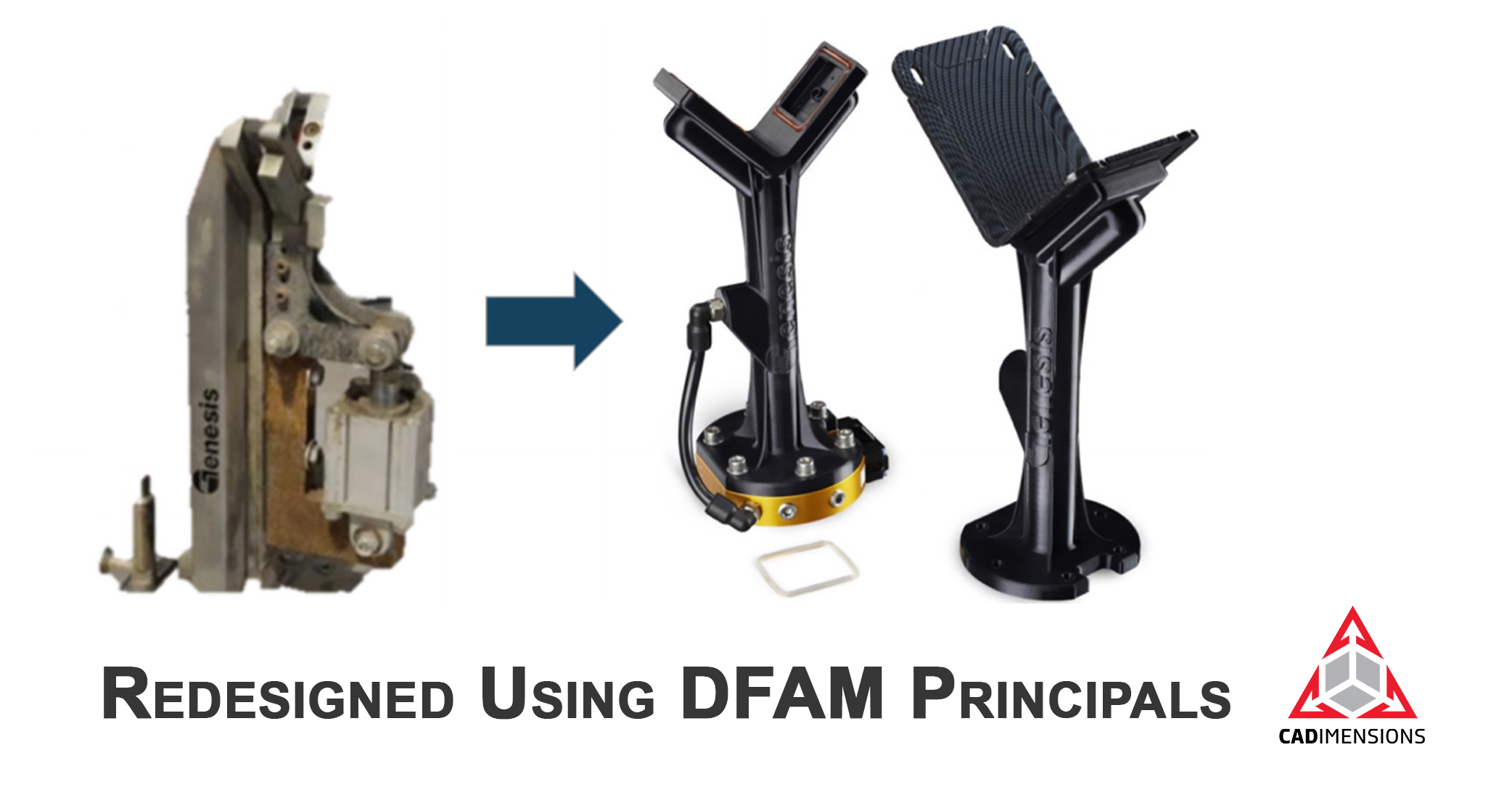
Another popular method used by those who require more complex fixtures is to use what’s called hybrid tools. These hybrid tools incorporate things like metal fasteners, hydraulics, hose lines, and other necessary attachments for more advanced applications.
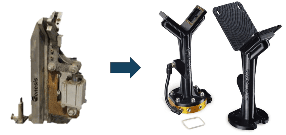
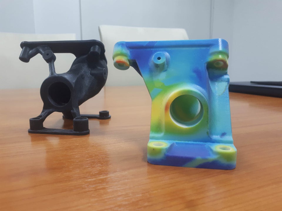
This example from Genesis Systems shows a traditional manufactured end-of-arm tool next to a redesigned 3D printed tool that incorporates air lines and metal fasteners. Genesis was able to greatly reduce the weight of the tool allowing them to use a faster, smaller, less expensive robot for this application.
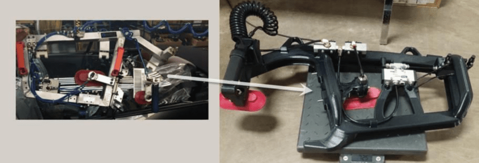
This next example comes from Ford. The original tool on the left is created out of aluminum and is used to help operators install windows on their convertibles. This fixture was very bulky despite being made from aluminum. It would also damage the car’s paint job if not controlled, causing a delay and extra cost. The 3D printed redesign on the right incorporates the same necessary air lines and fasteners while utilizing internal ribs for support. The new 3D printed design weighs less than 7.5 pounds.
Design For Additive Conclusion
Wrapping everything up, we talked about:
- Traditionally manufactured tools and how both our manufacturing methods and feedstock drive our design choices. We talked about the desire to reduce lead times to get parts as well as the main restrictions being machine availability and skilled labor.
- Even when using traditional designs, companies still see benefits by switching to additive manufacturing. These direct printed designs usually improve in lead time, cost, and overall ergonomics due to light-weighting.
- Misunderstandings about the phrase “design for additive manufacturing”, like how the term is overly broad. We looked at the common mistakes of hollowing and shelling when using FDM printing technology.
- Finally, we went over 6 easy design tips you can implement on your future designs to further reduce time to part, cost of the part, and improve overall functionality
Optimize Your Designs For 3D Printing
From Concept To Production. CADimensions Can Help You Every Step Of The Way