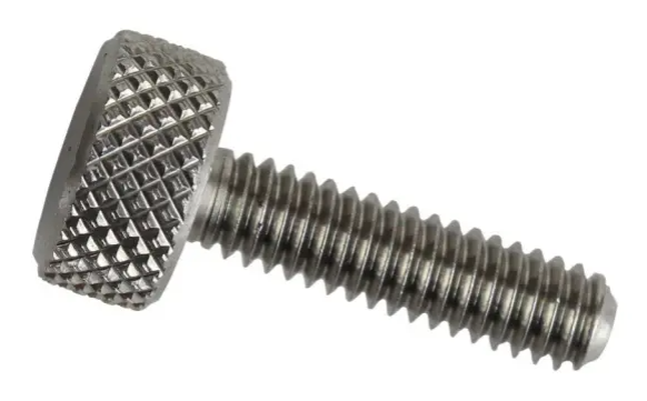
Knurling is a method of creating textured faces on a part, typically to ensure tactile feedback. It allows a person to know they are gripping something. Textured or knurled surfaces are easier to grasp, turn, or hold on to.
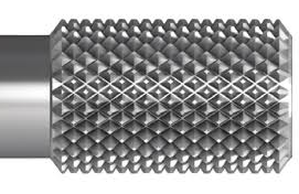
Modeling knurled surfaces in SOLIDWORKS can be challenging from a modeling perspective, but also from a performance perspective. Creating an individual “knurl” on a flat surface is easy, but tricky if the surface is a free form shape. Patterning hundreds or thousands of small bumps can incur a significant performance cost. What to do?
Modeling Versus Machining
From a practical standpoint, it may not be necessary to model knurling at all. Use a hatch pattern to indicate where the knurling should go on the drawing and call out what size the knurling should be. Let the machinist figure it out from there. They likely have a much better idea of how to create the knurling anyway.
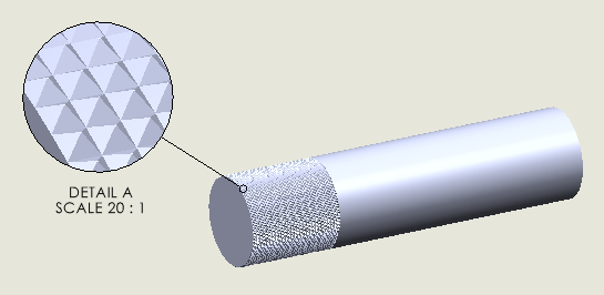
If dimensions and orientation are important, model a small portion of the knurled area. All that is needed on a drawing are enough of the important details to machine the knurling and manufacture the part. Rarely does all of the knurling need to be modeled like it is in this next image (see Example A).
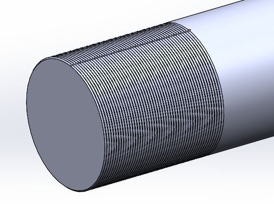
If you’re unconvinced of the performance ramifications, please refer to Example A. The knurls on this particular part were created with a revolved “V” cut which was then patterned up the length of the cylinder approximately one inch. The groove cut is .020″ wide at the top and there are 50 instances in the pattern.
The next “V” cut was straight down the length of the cylinder and ending just after the last instance in the first pattern. The result is shown in the next image. Nothing serious so far, and the rebuild performance is still quite acceptable.
But I Need It!
There may be times when modeling some sort of knurling or textured finish becomes necessary. If machining will be accomplished directly from the model, using a drawing to get the pertinent details to the manufacturer is no longer an option. If a model will be 3D printed, it will be necessary to model the texture. If the texture cannot be modeled by any standard means, machining or 3D printing the model becomes a serious problem.
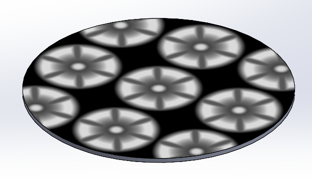
This is where the 3D Texture tool comes into play. The 3D Texture tool starts with a simple raster (bitmap) image that is applied to a model, or some face of the model. The bitmap is gray scale, such as that shown in the following image. Eventually, we will show how SOLIDWORKS uses the bitmap to create a 3D texture. In short, black becomes the valley floor, white becomes the mountain peaks, and gray falls somewhere in between. More on this shortly.
Applying an Appearance
The first step in creating a 3D Texture is to apply the appropriate appearance. Only certain appearances will work. To illustrate, we will use the model shown in the next image. The desire is to model a 3 point raised star shaped pattern around the outer face of the knob. The outer face is yellow in the following image for clarification.
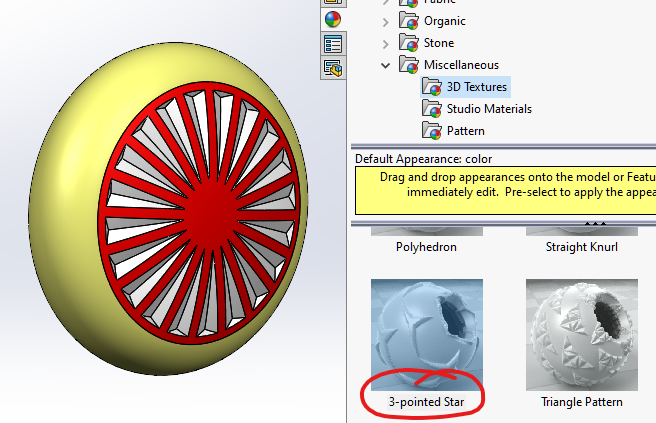
Using the “Appearances, Scenes, and Decals” tab on the Task Pane, expand the Appearances folder, the Miscellaneous folder, and then click the 3DTextures folder. These are your choices if your final objective is to model a 3D Texture feature. In our example, we will be using the “3-pointed Star” 3D Texture.
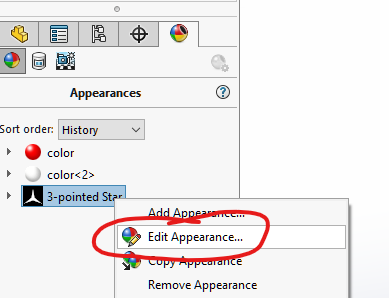
Using the standard process of dragging and dropping an appearance onto a model, the “3-pointed Start” appearance has been added to the face of the model. Some adjustments must still be made. To do so, click the DisplayManager tab at the top of the FeatureManager, click the “View Appearances” button if it is not already selected, then right-click the “three-pointed star” appearance and select “Edit Appearance…”. The following image shows how to navigate to the Edit Appearance command.
Settings Are Crucial
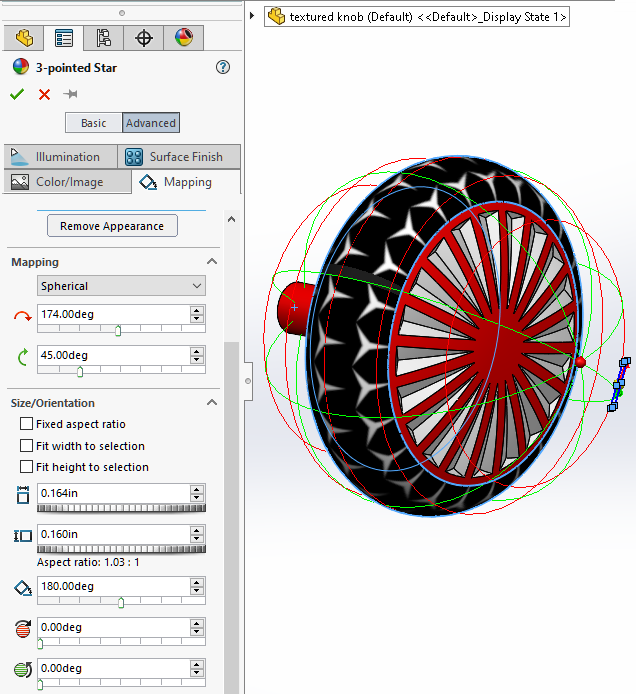
The Appearance PropertyManager is displayed upon editing the 3-pointed Star appearance. The Mapping tab is going to be the most important, shown in the next image. Alter settings as needed to create an appearance that meets your requirements. Notice the settings in the following image. It took some tweaking to get the white portions of the bitmap image to look uniform and exhibit good spacing on the outer face of the model. This is crucial if the final 3D texture is to have a good outcome.
After the bitmap image has been applied and tweaked to your liking, it’s ready to move to the next step.
3D Texture Tool
The 3D Texture command can be found in the Insert > Features menu. This command must be run on a specific body, so please select the body you wish to apply the 3D texture to. If there is only a single body in the part file (which is most common), click anywhere on the part.
At this point, an interesting thing happens; the entire body will turn into a mesh body. To convert the bitmap to a 3D texture, it is important to check any of the appearances listed in the Texture Settings list box (refer to the next image). Also make sure to check the checkbox labeled “Convert this texture to 3D”.
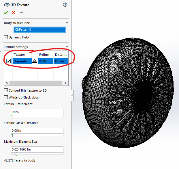
Earlier in this blog, it was mentioned the black areas of the original bitmap could be thought of as the valley floors, and the white areas were the mountain peaks. This can be reversed by unchecking the “White up Black down” option, should you deem it necessary.
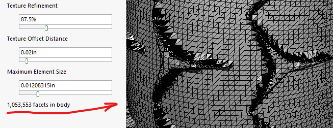
The three slider bars will help you in refining the appearance of the 3D Texture. “Texture Refinement” relates to the number of facets used to create the texture itself. “Texture Offset Distance” is the height of the 3D texture. Moving the “Maximum Element Size” slider to the right reduces the overall size of the facets making up the rest of the model.
Make adjustments slowly, and pay attention to the total number of facets listed at the bottom of the 3D Texture PropertyManager. It’s very easy to get well over a million facets with a couple tweaks of the slider bars. It will be necessary to weigh rebuild times with how refined the 3D texture should appear.
Did I Just Import Something?
Take a look at the top of the FeatureManager and notice there is a new Imported Graphic body (see the following image). The original solid body is still present. It’s just been hidden.
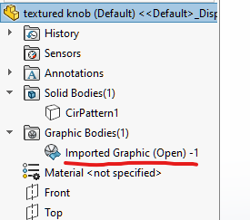
The graphic body is nothing more than a collection of facets. It’s essentially the same thing you’d get when exporting a stereo-lithography (STL) file. SOLIDWORKS created a mesh body of the part in order to “raise” the white areas of the bitmap into a 3 dimensional feature.
It’s important to understand the graphic body is not a solid body. There is no topological data and it cannot be used for machining. For that, there’s one more step.
Boundary Representations
Almost all solid modeling CAD systems available today, including SOLIDWORKS, are boundary representation (B-Rep) modelers. Every vertex of a solid model can be represented by an equation. Every edge of a solid model is bounded by 2 faces. A solid model is a closed volume. These are fundamental rules of a B-Rep solid model.
The solid model is defined mathematically. A graphic body is not. It’s just a bunch of triangles with no underlying mathematical equations representing the topology. When it is necessary to machine from a model, the model must contain mathematical information. Otherwise, the computer aided machining software will not have enough data.
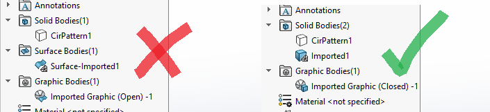
We are now ready to attempt turning the Imported Graphic body into a B-Rep body, but there is a roadblock. The name of our graphic body is followed by the word “Open” in parenthesis. That tells us our graphic body is not air tight. Ideally, this should read “Closed”. It may not be possible to transform the body into a B-Rep model.
When the graphic body is open, editing the settings related to the 3D Texture appearance, or editing the 3D Texture feature and adjusting those settings, may yield better results. However, it may not be necessary. On occasion, an open graphic body can still be turned into a closed B-Rep mesh body. It’s worth trying first before you start tweaking settings.
Creating The Mesh Body
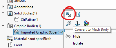
To convert the graphic body to a mesh body, right click the Imported Graphic object in the Graphic Bodies folder shown in the next image, and select the Convert To Mesh Body command. Leave the “Group Facets into Faces” option checked (not shown) and click OK.
If the Graphic Body was successfully converted into a solid body, there will be an Imported body listed in the Solid Bodies folder. If the process failed, there will be a Surface-Imported body listed in the Surface Bodies folder.
There’s A Catch
B-Rep mesh bodies are not quite as flexible to work with as standard solid bodies. There is a full list of feature types that are supported for mesh bodies in the SolidWorks Help, so I won’t repeat the list here. Suffice to say it’s best to leave using the 3D Texture Tool command to the end of the design process.
Having stated that caveat, it’s possible to create a separate solid body on which to create the 3D texture. In this way, the creation of the 3D texture will not limit in any way what can be accomplished with the rest of your solid model. When you are ready, add the two bodies together using the Combine command. You can have your cake and eat it, too!