This document will show how to create opposite hand components from an existing part and the steps needed to allow feature details to be transferred to the new part when detailing.
Before we get started - You will need the following
- Solidworks
- A part in need of its opposite hand version
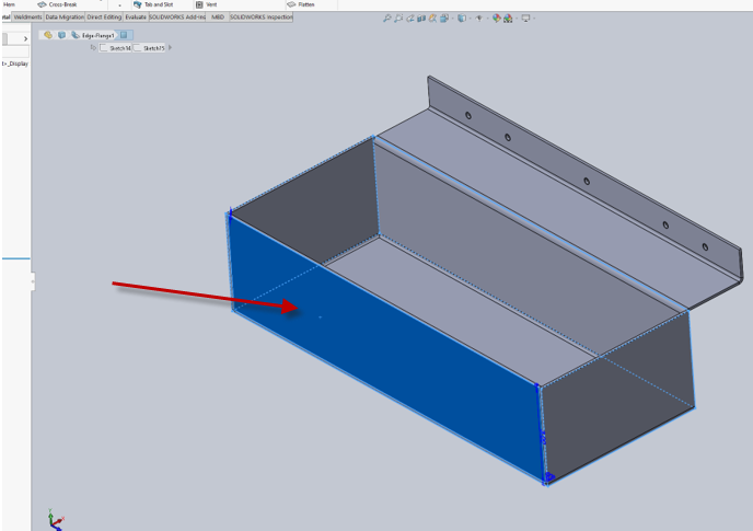
1. Start with the component to mirror
Select the part face to be used as the mirror by clicking it with your mouse.
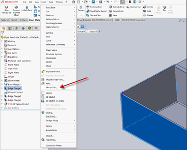
1.1 Create the opposite hand component
Select Insert and find Mirror Part in the list and select it.
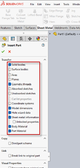
1.2 Selecting Properties
Select the properties to be transferred to the new part then select OK. These selections may vary depending on the type of part and the features used in the design.
In this example we have a sheet metal part that also contains features created with the hole wizard. So, add both Sheet metal information and hole wizard to the items selected.
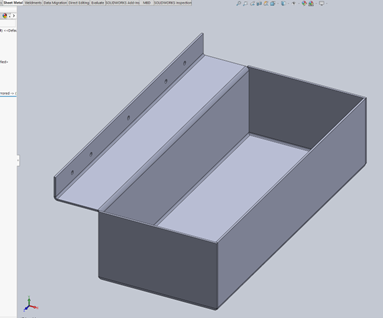
1.3 Save your new part
Now that your part is created save and name your part.
2. Create your drawing
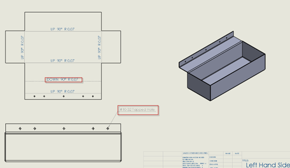
Your drawing will now allow you to show hole callouts, bend lines and other properties you selected to be transferred from the original part.
Not working like it should?
If you find you are still having issues creating opposite hand components, please contact CADimensions Technical Support for further assistance.
If you have an existing case, please contact the Application engineer you were working with; otherwise submit a new case online.