Gauge Tables Provide Consistency and Reduce Errors
Let’s start this article with an imaginary engineering department of 10 SOLIDWORKS designers at a sheet metal fabrication facility. Divide the department in half. One half will be required to manually plug in numeric values for material thickness and bend radius. The other half will be able to select predefined values from drop down menus. Which half of the engineering department do you think will make the most errors?
It is not a trick question, and the answer should be obvious. When SOLIDWORKS users are manually entering data based on memory, scribbled notes, or some other form of documentation, the chance of human error increases.
Interface Differences
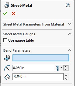
Without a gauge table, the input must be manually entered for material thickness and bend radius. An example of this interface is shown in Image 1. There is also the matter of bend allowance, which is not shown in the image. That value must be supplied as well, in one form or another (bend deduction and K-factor are a few other choices).
When using a gauge table, the values no longer need to be input manually. The thickness (gauge) can be selected from a drop down menu. The bend radius values are then displayed for the desired thickness. Bend allowance or K-factor is predetermined and supplied by the gauge table.
Gauge Table Location
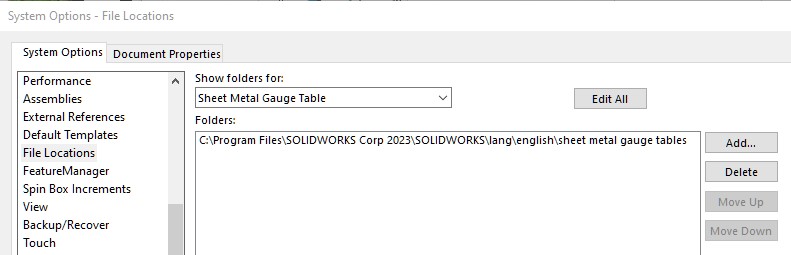
Use the File Locations section of your SOLIDWORKS Options (Tools menu > Options) to see where your gauge tables are located. An example of this is shown in Image 3. The default location is “C:\Program Files\SOLIDWORKS Corp\SOLIDWORKS\lang\english\Sheet Metal Gauge Tables”. Your installation folder for SOLIDWORKS may be different. Therefore, your folder location for Sheet Metal Gauge Tables may be different as well.
There are a few stock gauge tables. Using Microsoft Excel, open a gauge table and make changes as needed to suit your needs. The format is very straightforward and will be explained in the next section.
Modifying A Gauge Table
The sample stock gauge table we will look at for this article is named “sample table - steel - english units.xlsx”. Upon opening the gauge table, you will see what is shown in Image 4.
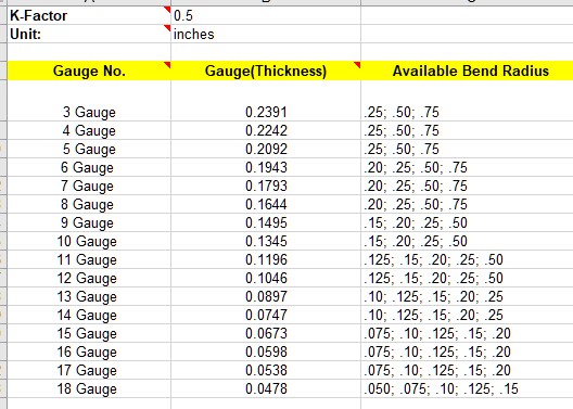
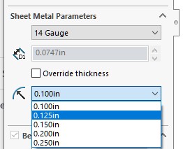
There are 2 settings in the top left corner, which are the K-factor and Units. They can be set as needed. Don’t modify the yellow row. That text is read by SOLIDWORKS so it understands what the columns are used for. The Gauge No. and Available Bend Radius columns are displayed as drop down menus. The Bend Radius menu (see Image 5) will display the values in the cell which relate to whatever gauge is selected.
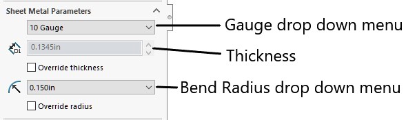
Using Image 5 as an example, and basing it on the table shown in Image 4, we can see how the gauge table works out for us. Gauges 3 through 18 will appear in the Gauge drop down menu. In Image 5, Gauge 10 was selected. This equates to a thickness of 0.1345 inches, as dictated by the table. Since the gauge selection drives the value, the Thickness setting is grayed out and cannot be altered directly unless the “override thickness” checkbox is selected.
The values in the Available Bend Radius column associated with the 10 Gauge row are .15, .20, .25 & .50. These values appear in the Bend Radius drop down menu (only one of which is shown in the image). Maintaining the proper formatting in the Available Bend Radius column is important. Use whatever precision is necessary, but make sure to separate each value with a semi-colon and space.
Gauge Table Implementation
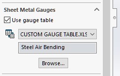
To use your new gauge table, copy the file to the location specified in your File Locations (mentioned earlier). When creating your sheet metal model, check the option to “Use gauge table” in the PropertyManager, and shown in Image 6. This would normally be done when creating the first Base Flange feature. Other Sheet Metal commands will have this same capability.
Gauge Table Variations
The gauge table used in this article was derived from the “sample table - steel - english units.xlsx” file supplied with SOLIDWORKS. There are other spreadsheet gauge tables that have somewhat different formats. You may find the format discussed in this article to be a bit more user friendly. However, you may find the other formats offer better control over bend allowance or K-factor on a wider range of bend angles.
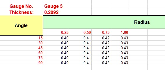
A portion of an alternative format gauge table is shown in Image 7. Using this format, there is a section for each gauge. Only one section is shown in the image, but there can be as many as needed depending on the number of thicknesses desired. Each section becomes a choice in the Gauge drop down menu. The columns for each radius value become selections in the Bend Radius drop down menu. The angle values are not listed anywhere in the Sheet Metal PropertyManager, but are used by SOLIDWORKS to determine what the bend allowance or K-factor should be.
When using gauge tables, the general (and obvious) advice is to always copy one of the existing stock tables and modify it to meet your requirements. You really can’t go wrong as long as the format is maintained. However, if using one of the alternative gauge tables that contain angle values (such as that shown in Image 7), make sure there are enough angles listed to accommodate the range of angles used in your manufacturing process.
Happy Modeling!