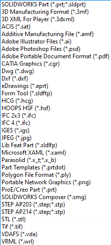
SOLIDWORKS provides many options for saving out your files. But what do they all do? Why are there so many? What’s the difference between a STEP file and a STL file? In this article I’ll be discussing each of the file types SOLIDWORKS Part files are capable of saving, with particular emphasis on the Universal 3D Modeling files commonly used to transfer components between different programs.
This is a continuation of Part 1, which can be found here, regarding how to move part files from newer versions of SOLIDWORKS to older versions, but it’s not necessary to read that article before reading this one.
As an extension of a previous article (and largely to sate my own curiosity), I sought to test which was the best Universal File Type to import as a part into SOLIDWORKS. I conducted an experiment using a moderately complex part file from the SOLIDWORKS 2023 Essentials course, saved it as every available file type on the dropdown list, then attempted to open them one by one inside of SOLIDWORKS 2021 to see how they would behave. Then I researched each of the file types to understand what each file was likely to contain, and what to expect when trying to open said file.
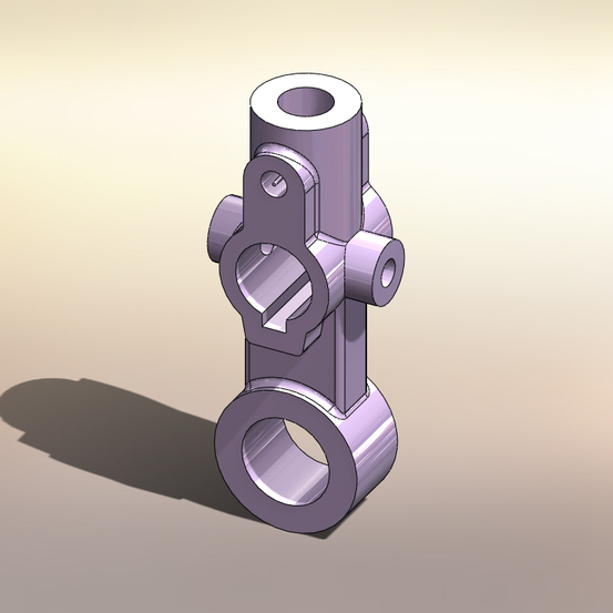
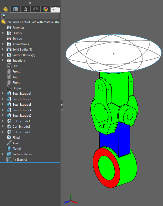
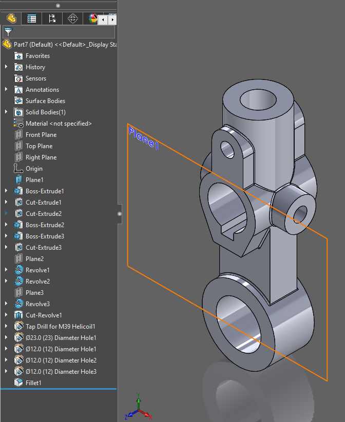
I started with the Idler Arm from the Essentials course. Then, I modified the part to determine what features would exist after the file type change.
| Feature | Trait measured |
| An axis through a vertical cylindrical face | Reference Geometry |
| A plane over the top of the part | |
| A circular surface body on the plane | Surface bodies |
| A material of oak wood | Material |
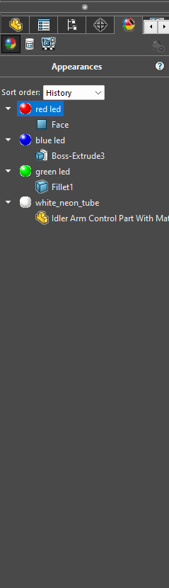
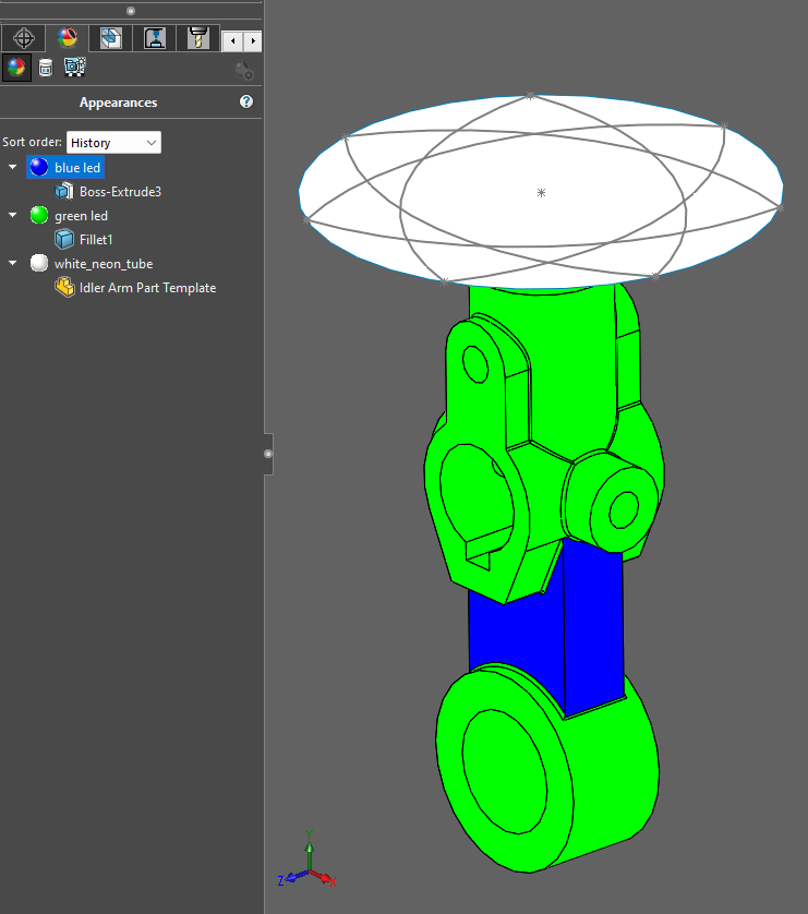
| Four different kinds of appearances: | |
| Red LED applied to the circular face at the bottom ring of the part | Appearances applied to Faces |
| Blue LED applied to the Boss Extrusion feature emerging from the ring | Appearances applied to Features |
| Green LED applied to the Idler Arm Body | Appearances applied to Bodies |
| White_Neon_Tube applied to the entire component | Appearances applied to Components |
which all the other file types were saved
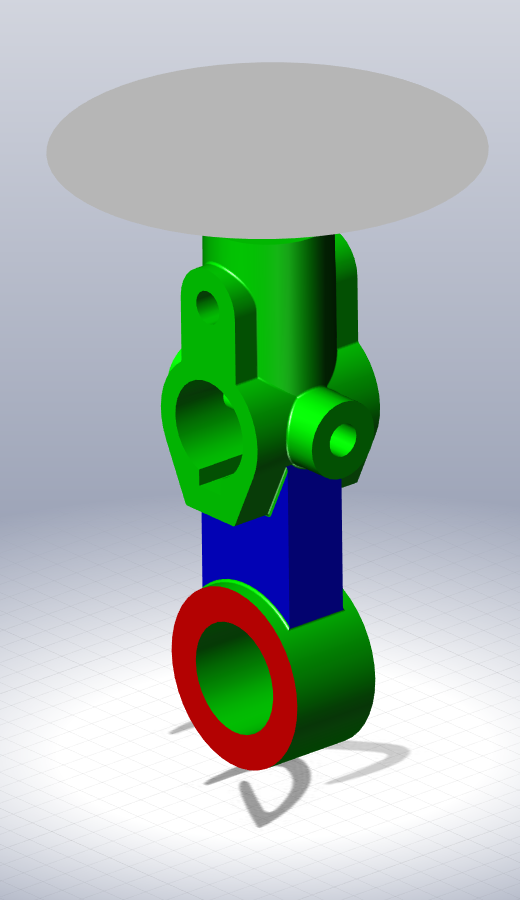
the Control Idler Arm
The resulting model, while visually quite garish, provided a solid basis for comparison to see what was and was not lost in the various transfers. As such, here are the results, categorized by general output type, and sorted by their order in the SOLIDWORKS “Save as type” List.
SOLIDWORKS-Exclusive File Types
| Name | Extension | Details |
| SOLIDWORKS Part | *.sldprt | Standard SOLIDWORKS Part File |
| eDrawings | *.eprt | Standard eDrawings file. |
| SOLIDWORKS Form Tool | *.sldftp | Tools specifically designed for sheet metal stamping and cutting features within SOLIDWORKS. |
| SOLIDWORKS Library Feature Part | *.sldlfp | File type for a standardized set of common components within the SOLIDWORKS Toolbox. (Fasteners, bearings, Injection pins, etc.) |
| SOLIDWORKS Part Template | *.prtdot | File type to create Part Templates. |
| SOLIDWORKS Composer File | *.smg | Standard Composer file type. |
These types of files were originally designed by Dassault Systèmes, and generally do not transfer well to other platforms directly. Similarly, none of these file types support forward compatibility. Trying to open any of these file types in a version of SOLIDWORKS that’s older than the version you’re using results in a Future Version error.
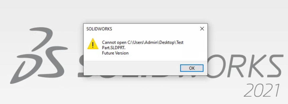
If you are encountering problems with Future Version errors, please see my previous article.
However, if the files are opened in SOLIDWORKS 2023, the version in which I created the original test file, that error does not persist. The files act about as expected. The SOLIDWORKS Part file opens normally and retains all the tested properties, of course. The eDrawings file refuses to open in SOLIDWORKS, but eDrawings itself opens it without issue. It even seems to retain all four of its Appearances.
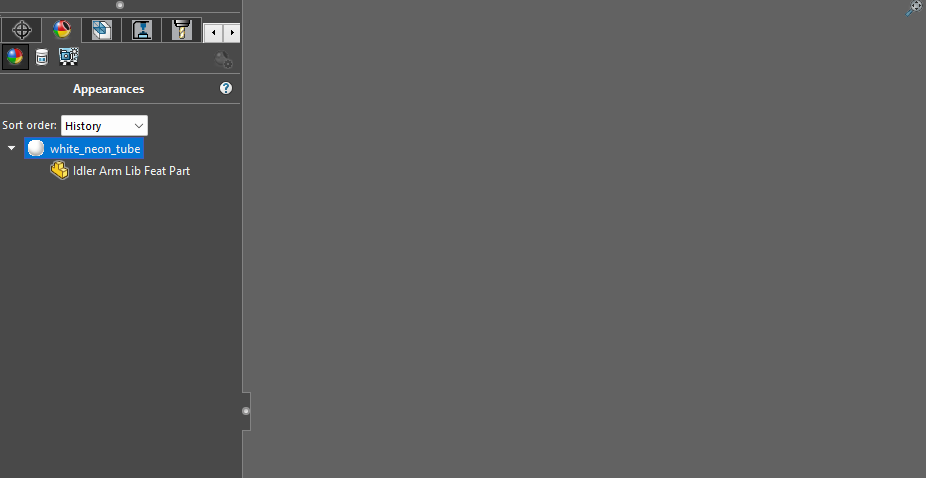
Oddly, despite the Library Feature Part and the Form Tool sharing similarities in their intended use, they responded very differently to being reopened in 2023. The Library Feature Part opened a completely empty document that somehow managed to retain the White Neon Tube appearance that was applied to the entire component, despite there being no bodies present. Meanwhile, the Form Tool opens exactly like the original Part File. I can’t seem to find any differences between the two. Perhaps this is because of simply saving the part directly in the Form Tool format instead of running the process correctly via the Forming Tool command.
The Part Template was interesting. It retained the main solid body of the part, as well as the reference geometry, surface body, sketch, and most of the appearances. The only thing it lost was the Red LED appearance applied to a Face. Given that it’s a template, it makes sense that it’s managed to keep nearly all its features. But I found the missing face appearance interesting, since it still retained appearances applied to Features and Bodies.
And finally, the Composer file opened perfectly fine within Composer, and refused to open at all in SOLIDWORKS.
Neutral 3D Modeling File Types
| Name | Extension | Details |
| 3D XML for Player | *.3dxml | Contains 3D-Image modeling info, with a lot of additional information. It’s how several 3DX apps store 3D design data. |
| ACIS | *.sat | 3D Modeling files created with the ACIS kernel. Native to AutoCAD, Mechanical Desktop, and early versions of Inventor, among other software. |
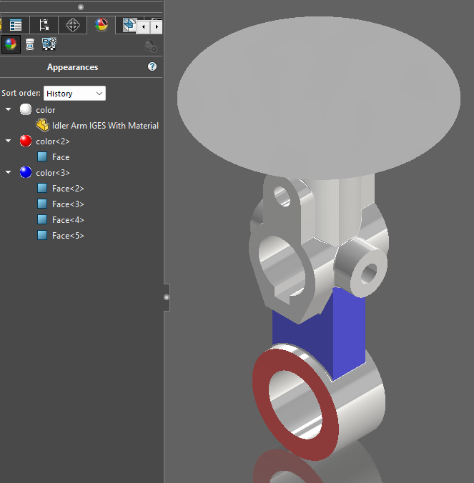
| IGES | *.igs | Initial Graphics Exchange Specification. Focused on wireframe but includes other solid modeling data as well. This format does not translate especially well to SOLIDWORKS. |
| Parasolid | *.x_t / *.x_b | Native kernel to SOLIDWORKS. Translates most cleanly and effectively but does not retain modeling history or certain other features. |
| ProE / Creo Part | *.prt | Native kernel to ProE and CREO. Seems to work OK for SOLIDWORKS as well, at least in my experience. |
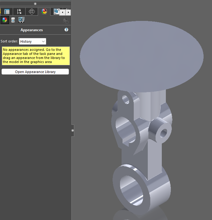
| STEP | *.step/*.stp | Good choice for file transfer between programs. Retains more information than many of its counterparts. |
| VDA-FS | *.vda | Verband der Automobilindustrie – Flächenschnittstelle, a file type that was apparently superseded by STEP files. Much of my research indicated this was a type of image file, I was surprised to see it successfully open in SOLIDWORKS. |
These file types, also sometimes known as “Universal” file types, are generally designed to communicate modeling information between different 3D modeling software. SOLIDWORKS naturally thinks in the Parasolid modeling format, so if you are importing a part or assembly from an outside location, that file type is least likely to cause quirks in the imported model. Beyond that, STEP files are very common, and generally play nicely with SOLIDWORKS. And I’ve personally found that ACIS (*.sat) files and some Creo Part (*.prt) files also tend to work relatively well.
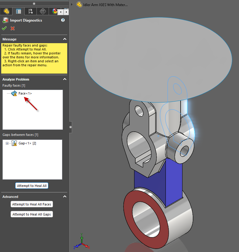
File types other than those three are a bit of a gamble. IGES files consistently import successfully, but IGES Kernel is quite unlike the Parasolid Kernel. As a result, these files are especially prone to developing strange quirks. Gaps splitting seams between surfaces, small deviations in intended geometry, surfaces that aren’t curved in quite the same shape as the original design, that sort of thing. In my experiment, a relatively simple part made in SOLIDWORKS, saved as an IGES file and then opened back in SOLIDWORKS somehow produced a faulty face. I would avoid IGES with regards to SOLIDWORKS, if possible.
Additionally, while everything I’ve researched indicates that 3DXML files fit this category of Universal 3D Modeling File, 3DXML files do not open with SOLIDWORKS at all. Even 3DXML files originally made inside of SOLIDWORKS won’t open back up with SOLIDWORKS. They are designed for representations of CAD models in the 3DEXPERIENCE Platform and are not compatible with SOLIDWORKS.
So, in short, if you are trying to import a model from an external source, (or even just a future version of SOLIDWORKS,) and you have your choice of file type, I would prioritize as such:
- Parasolids (*.x_t / *.x_b)
- STEP files (*.step/*.stp)
- ProE / CREO Part files (*.prt)
- ACIS files (*.sat) (but rank higher if Appearances are important)
- IGES files (*.igs) (Expect problems to emerge in the translation)
For any of the other file types, consider yourself lucky if they open without issue in SOLIDWORKS. But, that said, if you find a file type that consistently works well for your specific purpose, then great! Keep using that one.
Additionally, here is a table detailing some info about how these files opened in the experiment (the Appearance Key can be found below the table):
| File Type | Import Diagnostics | Feature Recognition? | Reference Geometry | Surface body | Sketch | Material | Appearances |
| 3D XML | File does not open | ||||||
| ACIS | Yes | Yes | No | Yes | No | No | All* |
| IGES | Yes | Yes | No | Yes | No | No | C, Fa, Ft -> Fa |
| Parasolid | Yes | Yes | No | Yes | No | No | All* C -> B B Ft -> Fa Fa |
| ProE / Creo Part | Yes | No | No | Yes | No | No | C Ft -> Fa F |
| STEP | Yes | Yes | No | Yes | No | No | None |
| VDA-FS | Yes | Yes | No | Yes | No | No | None |
Did it give a prompt for Import Diagnostics? | Did it give a prompt for Feature Recognition? | Did it retain Reference Geometry? | Surface bodies? | Sketches? | Materials? | What Appearances were retained, and in what way were they applied after the transfer?
In the Appearances column,
All indicates that all of the appearances were retained in one form or another.
C indicates that the Component appearance (White_Neon_Tube) was retained by this file type.
B indicates the Body appearance, (Green LED) was retained by this file type.
Ft indicates the Feature appearance (Blue LED) was retained by this file type.
Fa indicates the Face appearance (Red LED) was retained by this file type.
X -> Y indicates the appearance was retained, but applied to a different facet of the component. For example, C -> Fa indicates that the Component appearance was retained, but was instead applied to all of the faces to which it applies.
Finally, * indicates there was some additional consideration or quirk on the imported part, as discussed below.
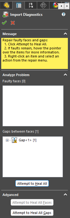
Import Diagnostics is a great tool for finding tiny problems with the import process. It’ll tell you if there are edges that don’t quite align between surfaces, small breaks that could never exist in a real part, and other such errors. I would encourage its use on every component you import. For this experiment, every file type that opened asked if I wished to run Import Diagnostics, and every time I ran it, it consistently did not like the open edge of the Surface Body. But no other issues emerged from the transfer.

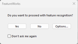
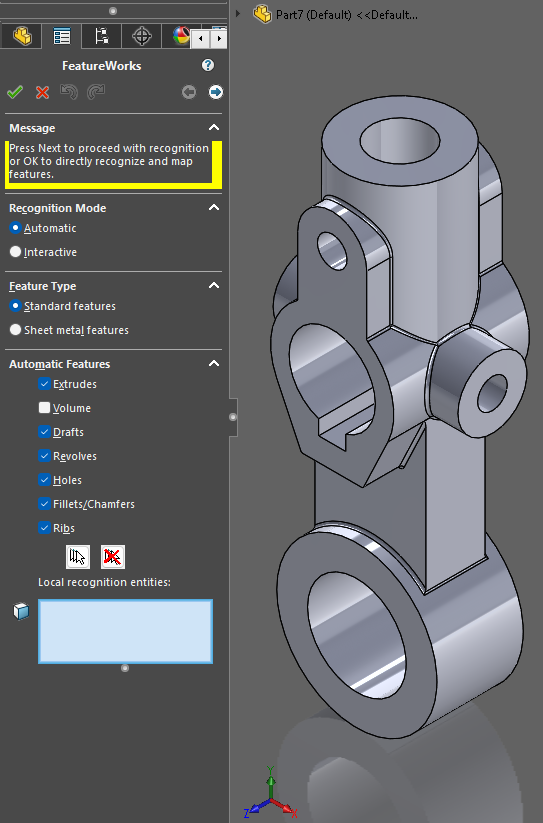
The option for Feature Recognition appeared for every file type except 3DXML (which didn’t open) and the Creo Part file. I explain more about what Feature Recognition is and how it works in my other article, but in short, if you let SOLIDWORKS perform Feature Recognition it will do its best to recreate the part itself. It doesn’t usually match the same design intent as the original part, but it does make it a lot easier to work with.
Surprisingly, every one of these files (that opened) retained the circular Surface Body placed over the component. That is, unless you went through with Feature Recognition, in which case the surface body was removed. Feature Recognition doesn’t seem to deal with Surface Bodies.
In every instance, Reference Geometry, Sketches, and Material all went unsaved. These are all data exclusively contained with the original SOLIDWORKS Part file, and none of these options support the transfer. It’s worth mentioning that Feature Trees are never saved with any of the universal part files either. Those are SOLIDWORKS-exclusive data.
Some Appearances survived the transfer, though which ones survived varied by what file type was used. Even those appearances that did survive were sometimes changed or reapplied to a different facet of the part. But universally, Feature Recognition strips the component of any Appearances it had. If you intend to keep them, you will likely have to forego Feature Recognition, or reapply them after the fact.
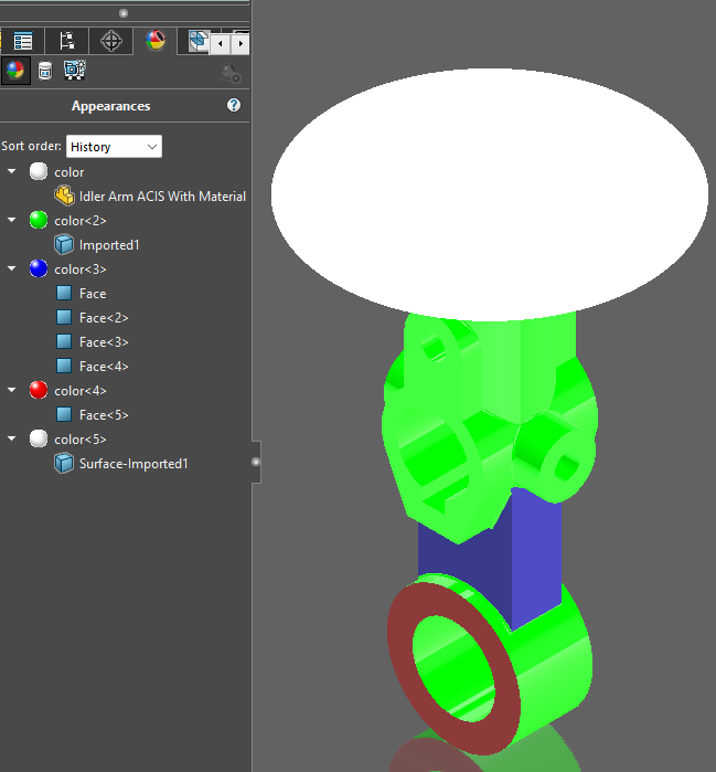
ACIS files retained appearances the best. No colors were lost, though their names were changed, their hues slightly shifted, and those Appearances originally applied to a Feature instead got applied to all the faces of that feature.
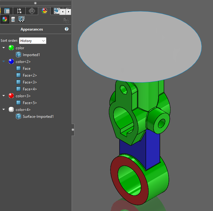
Parasolid files retained all appearances, but not unchanged. The Component appearance became a Body appearance, and the Feature appearance became multiple Face appearances, but it’s one of the only file types to retain all four colors. However, it did change the colors in question, converting the luminous LED and Neon colors into their simpler counterparts of simply White, Green, Blue and Red.
IGES files entirely dropped any appearances originally applied to Bodies, and all of those applied to Features became applied to Faces instead.
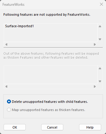
The Creo part has quite a few available import options, which mostly seem to determine whether or not you keep the surface body. If you choose to “Import geometry directly”, the separate surface body will be lost, but it will retain some of the appearances. On the other hand, if you choose to “Analyze the model completely”, and select Features as your import option, it will retain the surface body. The option “Import material properties” does not actually retain the material, but it does retain appearances. The options, “Import sketch/curve entities” and “Import geometry from hidden sections” did not actually import any of the promised data, and I have not been able to figure out their purpose. Regardless of import method, if “Import material properties” was checked, the model lost appearances associated with Bodies, and applied Feature appearances to faces.
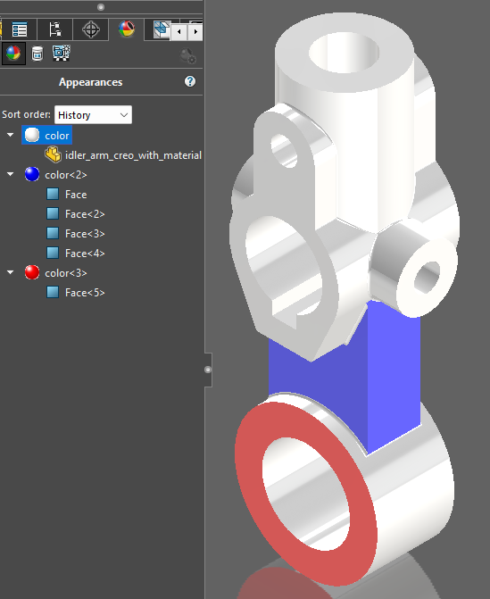
Import Geometry Directly, Knitting, and Try forming solid models, and all three Import options checked.
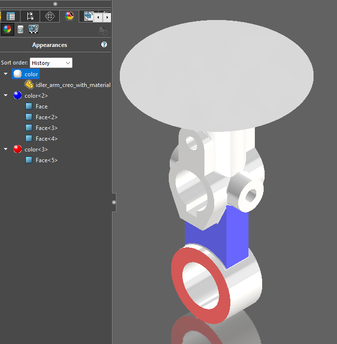
Analyze the model completely, all three Import options checked, and the Features option selected on the second window.
And finally, STEP and VDA-FS failed to import Appearances entirely.
Mesh File Types
| Name | Extension | Details |
| 3D Manufacturing Format | *.3mf | Remarkably dense with additional model details. Originally intended to replace STL, OBJ, AMF, and VRML. |
| Additive Manufacturing File | *.amf | Intended for 3D Printing, includes a fair amount of metadata. Intended to improve upon STL. Not dissimilar to XML in structure. |
| CATIA Graphics | *.cgr | Native to CATIA, CATweb, and DMU Navigator. These files contain only graphical information are inherently View Only. |
| IFC | *.ifc | Industry Foundation Class File. Originally intended for building design. It’s very poorly suited to SOLIDWORKS. |
| Polygon File Format | *.ply | Typically the output of a 3D Laser Scan. Mesh can include polygons other than triangles. |
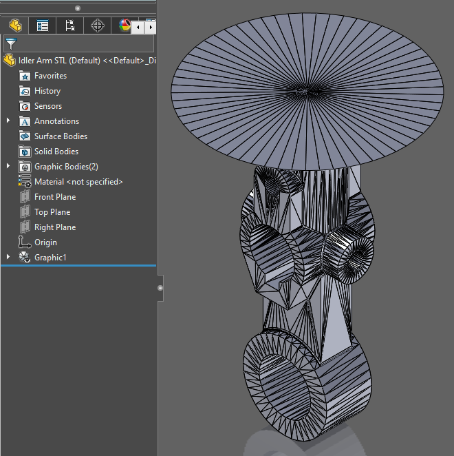
| STL | *.stl | Stereolithography files. By far the most common form of triangle mesh files. |
| VRML | *.wrl | Virtual Reality Modeling Language file. These are used for 3D visualization of objects in web environments or gaming platforms |
These files all generate as meshes of triangles approximating the original model. Extremely common for 3D Printing, CNC Milling, and other production or prototyping processes exclusively concerned with a close approximation of the outside surface of a part.
There are two reasons you may want to use triangular meshes over more mathematically ideal models. First, it’s relatively easy to check mesh bodies for gaps or overlaps, and second, it’s far easier to convert a model into 2D slices if every surface is planar and every edge is a straight line. As such, they’re most commonly used in 3D printing and a few other prototyping technologies, but are much less useful in standard modeling.
STL files are the near-universal standard for this sort of work. It’s the oldest format on this list, it contains little to no extraneous information making the file sizes relatively small, and it serves the purpose it’s intended to serve quite well. Like the QWERTY keyboard, it did not become the standard because it’s the best at anything, but because it’s the oldest and most well-known.
AMF files were designed to be slightly more suited to the task of 3D printing. They can store the arrangement of multiple separate objects, and a bit of useful metadata including author, copywrite details, special instructions, and some colors. It should also be noted that AMF files cannot be opened in SOLIDWORKS.
3MF is a further improvement on AMF, including additional info such as property information, material, thumbnail image, digital signatures, etc. In my research, these seem like the best option for storing data to send to a 3D printer. These files can be opened in SOLIDWORKS, though it seems SOLIDWORKS is not able to read all of its relevant data.
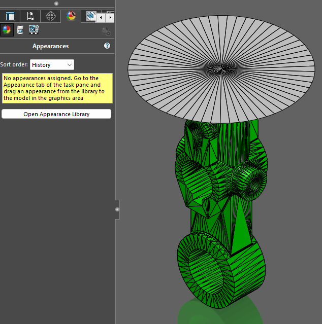
Polygon File Formats are unique in that they do not appear to generate strictly triangular meshes. They can have polygons of any number of edges instead. They were originally designed to store the data from 3D laser scanners, so the added adaptability makes sense. They can be opened in SOLIDWORKS, and seem like they retain a trace of the appearance applied to the Body, though the Appearance Manager shows no record of this.
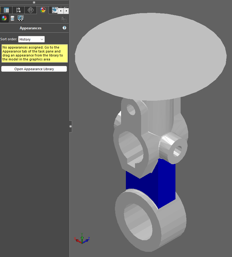
VRML files seem to be tied closer to the world of virtual reality design. I wasn’t able to find much information on these. The file did, however, open in SOLIDWORKS, and the blue rod indicated that appearances applied to Features will stick. What was interesting was that no matter which Display Style I chose to make the lines more visible, the component never changed its appearance to anything but this:
STL files may be the sort that everyone knows and understands, but perhaps give a 3MF file a try the next time you need to 3D print something.
Vector Graphics File Types
| Name | Extension | Details |
| Adobe Illustrator | *.ai | Stores vector image data for an Adobe Illustrator project. |
| Portable Document Format | Extremely common vector image data format for sharing a wide variety of documents. | |
| CAD Drawing File | *.dwg | The native file type for several CAD software including AutoCAD and Draftsight. |
| Drawing Exchange Format | *.dxf | Another CAD-based file type, more suited for communicating modeling information to other CAD programs. |
Vector graphics data can be a useful way to store visual information. Because the data is carried in mathematical equations and spatial definitions instead of a bitmap, there’s no detail loss or pixelation with the image. You could zoom in on it forever and retain perfectly clear edges. When attempting to represent CAD parts, assemblies, or drawings, (computer models largely comprised of straight lines, circular arcs, and the rare spline or conic curve,) vector graphics data can be a very effective means of storing, sharing, and presenting that information.
But SOLIDWORKS really does not like opening these files. When I attempted to open the Illustrator file it gave me an error saying that Adobe Illustrator version CS3 or later was required to import an Adobe Illustrator file into SOLIDWORKS. Strangely, I got precisely the same error, specifically mentioning Illustrator, when I attempted to open the PDF in SOLIDWORKS as well.
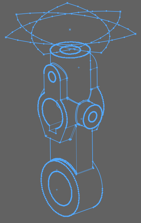
When I attempted to open the DWG and DXF files, they responded identically to one another. They both opened the DXF/DWG Import Wizard, providing a remarkably wide range of options for how, precisely, you would like to import your file. But even imported as a new part with the selection of 3D curves or models, it always imported as a 2D sketch of the screen as it was at the moment it saved.
Bitmap Image File Types
| Name | Extension | Details |
| Photoshop File | *.psd | Project files for Adobe Photoshop. |
| JPEG image | *.jpg | Image file type featuring higher compression rates and therefore smaller file sizes. |
| PNG image | *.png | Image file type featuring lossless compression and transparent image backgrounds. |
| Tagged Image File Format | *.tif | Generally rather large image files that are well-suited to storing very high resolution images. |
Contrary to the Vector Data files above, Bitmaps store an image as a large array of pixels. What they lack in infinite definition, they make up for in the complexity and detail of the images they can represent. However, for the purpose of saving to these file types from SOLIDWORKS, all of the ones I was capable of opening without specialized software, (JPG, PNG, TIF) opened essentially a screenshot of the workspace at the moment of saving the file. They are all essentially identical images to this one.
The Photoshop file acted very strangely, though. It opened a SOLIDWORKS part, created a sketch on the Front Plane, and then froze up. SOLIDWORKS sat there consuming 100% of my computer’s CPU for a solid 20-30 minutes. I returned to my computer to find that it had finally loaded, sticking this same image to my cursor as a Sketch Picture, and wanting me to drop the image where I wanted it on the Front Plane.
Miscellaneous Other File Types
| Name | Extension | Details |
| Highly Compressed Graphics | *.hcg | HCG files are optimized for transmission over the Web, specifically to be used by CATIA. |
| HOOPS SSF | *.hsf | HOOPS Stream Format, a form of High-compression document, like a .zip, specifically for 3D Data and Bitmap information. |
| Microsoft XAML | *.xaml | XAML generally seems to be a programming language focused on UI, but the code of this file reads like a 3D model. |
These last three file types could not easily fit into any other category. As far as I can tell, the only thing they have in common is that they each opened with an “incompatible type” error. But their fundamental structure and apparent purpose seem to be quite different from anything else on the list.
The HCG file is the most puzzling file type I’ve encountered in this entire project. The SOLIDWORKS help file says it is a “Highly Compressed Graphics” file optimized for sending 3D models over the internet, specifically to be used by CATIA. Lacking access to CATIA, I have never successfully opened one of these files in any program at all.
HSF also seems like a file type that I should be able to access in some capacity, but once again I have not managed do so. They apparently are associated with HOOPS Visualize and contain data about the graphical elements in a 2D or 3D model. And it appears to be optimized for streaming, taking up minimum bandwidth. Nonetheless, I have been unable to open the file to determine if it is, in fact, a 3D model, as I have not been able to open this file either.
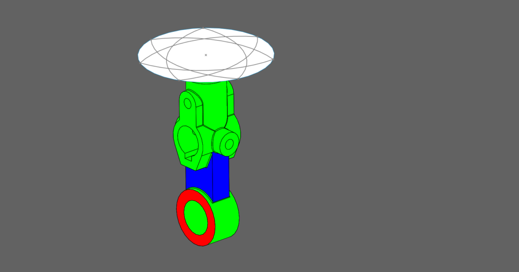
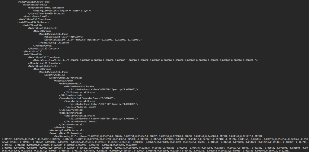
And finally, the XAML file. Once again I have no means of opening it properly, but when I open the file in Notepad it produces a surprisingly legible chunk of XML code that sure looks like it’s describing a solid model of some variety. It details camera position, background color, lighting, a very long list of mesh points, and quite a bit more besides. I suspect that if I were able to open it in something outside of Notepad, it would provide a triangular mesh body with a color scheme quite like the original part.
Conclusion
SOLIDWORKS has a very wide range of available file types, serving an even larger range of purposes. If you wanted to know which file type serves your project best, or just wanted to know what they do, then I hope this document could be of some help.
As always, If you are encountering any technical difficulties with SOLIDWORKS, please feel free to reach out to our Technical Support Team. We’ll be happy to help you.